
This article follows on from Whiteside’s Line: Throw it out and start again. In that article I explained why the anteroposterior axis (APA, Whiteside’s Line) is inaccurate because it doesn’t account for the three dimensional shape of the trochlear groove. If you haven’t looked at it I would recommend going there first then come back to this article.
In this article I’m going to show you how to correct for the error during surgery by using the Sulcus Line / STAG technique. I will also go over the evidence that it works from our published CT and cadaver studies and the results of the clinical trials.
When we reference the trochlear groove to set our femoral component rotation we are hoping to match the rotational alignment of the patellofemoral joint. (See Femoral Rotation : When the Gold Standard is a bit rubbish for further discussion on the associations between landmarks). To do this we need to isolate the rotational component of the trochlear groove.
Here’s the way to do it:
- Find the floor of the groove. (See video, Figure 1) Start posterior above the notch. Palpate the groove by sliding your thumb along it. Follow your thumb with a diathermy marking multiple points along the deepest part of the groove. Posteriorly you will notice that the deepest part of the groove is often lateral to the centre of the intercondylar notch – don’t worry, this is not Whiteside’s Line so you don’t have to start in the centre. At the proximal / anterior end of the groove it often becomes indistinct or can veer off medially or laterally, (Figure 2) due to arthritic damage or anatomical variation. Again, don’t worry you don’t need this part. Ignore the proximal 1 to 2 cm of the groove. Fill in the gaps with the diathermy to make a complete curve along the deepest parts of the groove.
Figure 1. Marking the floor of the trochlear groove.

Figure 2. Proximal end of trochlear groove often diverges and should be disregarded.
So far so good. I’m guessing that a lot of you are thinking that this is pretty much what you’ve been doing anyway so your probably not that impressed. The reason is the next bit.
If you do the distal femoral cut next you will lose the accuracy of the Sulcus Line. The advantage of the SL over the APA is that you can see the coronal direction in which the groove is running. By adjusting for this direction you can remove parallax errors and isolate the rotational component of the trochlear groove. Look back at Whiteside’s Line: Throw it out and start again for the 3DCT recreations of this error occurring. As a sample look at Figure 3 which shows the APA viewed from two different directions – the same femur, same points but two different angles. Then look at the video (Figure 4) with the Sulcus Line marked in and see how we change the direction we are looking until we are looking along the line of the groove. The rotation of the groove can only be isolated when looking along the groove in this direction. It’s simple trigonometry – if you want to isolate the vector in one plane you need to take the other planes out of the equation.


Figure 3. The angle of the APA relative to the SEA changes depending on the direction we are looking at the femur.
Figure 4. By marking in multiple points along the floor of the groove (Sulcus Line) we are able to determine the direction at which we are looking along the coronal direction of the groove.
Once you do the distal femoral cut the parallax error comes back again. Have a look at Figures 5 and 6. The distal femoral cut is (let’s assume) perpendicular to the mechanical axis in the coronal plane, but the trochlear groove is likely to be running in a different coronal direction.


Figures 5 and 6. Block is flat on the distal femoral cut. This is how most people align a sizing guide or cutting block with the trochlear groove during surgery. The distal femoral cut is perpendicular to the mechanical axis. The Sulcus Line of the trochlear groove runs in a different coronal direction. If you put a block flat on the distal cut surface (Figures 5 and 6) you are not aligned with the trochlear groove so a parallax error occurs.


Figures 7 and 8. Block is aligned with the trochlear groove in the coronal plane – not flat on the surface (the pins are inserted back into the STAG pinholes to show that we are looking along the line of the trochlear groove – note that the STAG is always used prior to the distal femoral cut, these pictures are just to show the parallax error). The blue pen marks were made under the block in Figure 5.
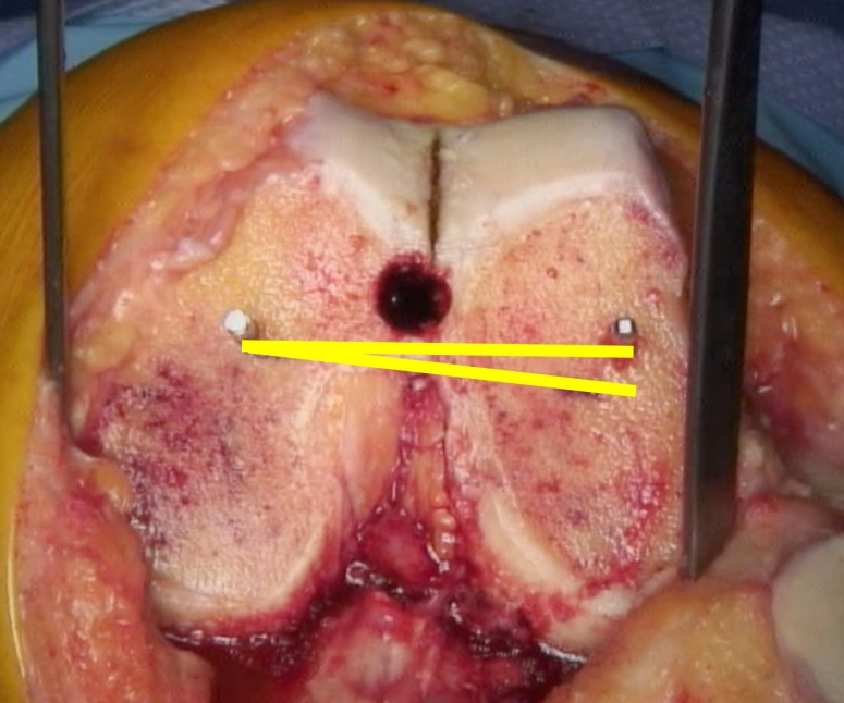
Figure 9. The difference between the yellow lines is the parallax error.
If you try and reference the Sulcus Line after the distal femoral cut the size of the parallax error is frequently around 5 degrees and can be over 10 degrees.
We don’t want to cut the distal femur perpendicular to the trochlear groove as it would make for some very varus or valgus knees, so what we need is a way to transfer the rotation of the trochlear groove onto the planned distal femoral cut. So we’ve designed a simple instrument that allows us to do that. We’ve called it the Sulcus Line of the trochlear groove alignment guide (STAG, Enztec, Christchurch, New Zealand, STAG Enztec). The surgical technique is available on the website, or below, but I’ll go through it briefly now.
- Insert the STAG intramedullary guide. Place the STAG block over the flattened end of the rod. Line the block up with the Sulcus Line in both the axial (rotational) and coronal planes. Figure 10 and 11. Lining it up in the coronal plane removes the parallax error. Putting it over the intramedullary rod matches the flexion of the block to the flexion of the planned distal femoral cut which allows us to accurately transfer the rotation of the groove.
- Drill two pins through the parallel pin-holes in the STAG block. Figure 10 and 11.
- Remove the pins, the block and the IM rod.
- Perform your usual distal femoral cut (the STAG does not influence the coronal angle of your distal femoral cut).
- Find the holes on the cut surface of the bone produced by the pins. Figure 12.
- Use the pin-holes as a guide to femoral rotation.
The whole process takes about 30 seconds after the first couple of goes.


Figure 10 and 11. STAG block aligned in coronal and axial directions with the Sulcus Line

Figure 12. STAG pin-holes
Having designed this technique we have gone about assessing its accuracy. We started with a cadaver lab. We performed the STAG technique and several other ways of referencing the groove on 10 femora. The STAG technique was accurate and reproducible. It produced a range relative to the epicondylar axis of 6.2° (SD 2.0°) which was less than the 9.4° (SD 3.7°) produced using the same landmarks without the STAG device. This was published in 2016.[1]
We then proceeded to two clinical trials. We measured intraoperative photographs of the STAG pin-holes and Whiteside’s Line, and compared it to postoperative CT scans of the surgical epicondylar axis (SEA). Using the STAG produced a mean measurement of -0.5° (SD 2.3°, range -5.8° to +4.2°). Using Whiteside’s Line produced a mean measurement of 0.0° (SD 5.7°, range -10.2° to +17.6°). While the average results are very similar the range for APA (27.8°) is more than twice as large as for the SL (10°).
We measured the results of the using the STAG device in a further 90 knee replacements and got the same results for the SL / STAG technique with a mean of -0.7° (SD 2.3°, range -5.5° to +4.6°). This study also examined the relationship between the axial alignments of the trochlear groove and the posterior condyles. The conclusion was that many femora are rotational asymmetrical and therefore the rotation of both landmarks should be considered during surgery.[2] This will be discussed in a future article.
The key point I’m trying to make is that the parallax error that occurs when we reference the groove explains the highly variable results reported for the APA in the literature[3-6, 1] which lead Victor to describe it as “Inconsistent” with “Large variability”.[5] It is very difficult to predict and impossible to compensate for this parallax error without the STAG device. If you are currently referencing the trochlear groove in any way I would suggest you have a look at it. I will put links to all the papers and further videos at the end of the article. You can (or get your implant company to) contact Enztec via their website to have a look at a STAG instrument. I do hold a patent on it and do receive a very small amount of royalties, but I can assure you that my interest here is much more academic than financial.
The next article will be on the importance of femoral rotational asymmetry.
Links:
Youtube video: The parallax error during surgery
Papers:
- Talbot S, Dimitriou P, Mullen M, Bartlett J. Referencing the sulcus line of the trochlear groove and removing intraoperative parallax errors improve femoral component rotation in total knee arthroplasty. Knee Surg Sports Traumatol Arthrosc. 2015:1-8. doi:10.1007/s00167-015-3668-7.
- Chao TW, Geraghty L, Dimitriou P, Talbot S. Averaging rotational landmarks during total knee arthroplasty reduces component malrotation caused by femoral asymmetry. J Orthop Surg. 2017;12(1):74. doi:10.1186/s13018-017-0575-2.
- Siston RA, Patel JJ, Goodman SB, Delp SL, Giori NJ. The variability of femoral rotational alignment in total knee arthroplasty. J Bone Joint Surg Am. 2005;87(10):2276-80. doi:10.2106/JBJS.D.02945.
- Middleton FR, Palmer SH. How accurate is Whiteside’s line as a reference axis in total knee arthroplasty? Knee. 2007;14(3):204-7.
- Victor J. Rotational alignment of the distal femur: a literature review. Orthop Traumatol Surg Res. 2009;95(5):365-72. doi:10.1016/j.otsr.2009.04.011.
- Talbot S, Dimitriou P, Radic R, Zordan R, Bartlett J. The sulcus line of the trochlear groove is more accurate than Whiteside’s Line in determining femoral component rotation. Knee Surg Sports Traumatol Arthrosc. 2015;23(11):3306-16. doi:10.1007/s00167-014-3137-8.

2 thoughts on “Femoral component rotation: Find your groove more accurately”